
Part 8 of 10 in the series From Reservoir to Surface: Oil and Gas Production for Beginners. Previous part: Types of Artificial Lift.
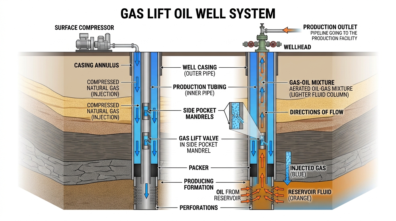
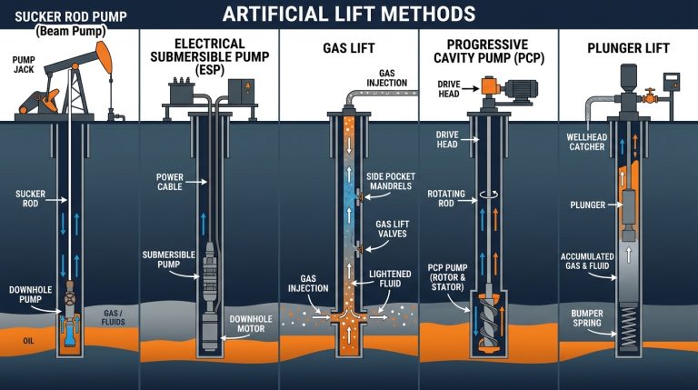
Gas lift is an artificial lift method that injects high-pressure gas into the lower part of the production tubing. The gas mixes with the oil and water, makes the fluid column lighter, and lowers the flowing bottom hole pressure. With lower bottom hole pressure, the reservoir pushes more fluid into the well, so the well produces again or produces more. The energy comes from a gas compressor or a high-pressure gas source at the surface, not from a pump in the well.
The Principle: Lightening the Fluid Column
The pressure at the bottom of a flowing well is roughly the sum of:
- Wellhead (back) pressure,
- The hydrostatic pressure of the fluid column,
- Friction losses in the tubing.
The hydrostatic part is usually the largest. A column of oil and water is heavy. When gas is mixed in, the average density of the column drops, so the hydrostatic pressure drops. A lower flowing bottom hole pressure means more drawdown on the reservoir and, following the IPR, a higher rate.
The Gas Lift System
A typical continuous gas lift system has these parts:
- Compressor station: raises the pressure of gas recovered from the separators.
- Lift gas manifold: meters and controls how much gas goes to each well.
- Injection into the annulus: gas enters the casing-tubing annulus at the wellhead.
- Gas lift valves: installed in side pocket mandrels along the tubing, they let gas pass from the annulus into the tubing.
- Production: the gas and well fluid flow up together to the separator. Gas is separated, recompressed and reused in a closed loop.
A packer seals the annulus at the bottom so injection gas can only enter the tubing through the valves. Read about mandrels and packers in Downhole Completion Tools.
Continuous vs Intermittent Gas Lift
Continuous gas lift
Gas is injected all the time at a single deep point. This is the most common method. Shell’s gas lift design guide states that continuous gas lift accounts for more than 95% of the company’s gas-lifted production. It suits wells with a reasonable reservoir pressure and productivity.
Intermittent gas lift
The well is allowed to accumulate a slug of liquid in the tubing. Then a large volume of gas is injected quickly under the slug to push it to surface. The cycle repeats. It suits wells with low reservoir pressure or low productivity. A variation, plunger-assisted intermittent lift, uses a plunger between the gas and the liquid to reduce liquid fallback.
Gas Lift Valves
Gas lift valves are small, spring-loaded or gas-charged valves that open and close depending on pressure. They are placed in side pocket mandrels and can be replaced by wireline without pulling the tubing.
- Injection pressure operated (IPO) valves: open mainly in response to the casing (injection gas) pressure.
- Production pressure operated (PPO) valves: open mainly in response to the tubing (production fluid) pressure.
- Orifice valves: a simple fixed opening with a check valve, usually used as the deepest operating point.
- Dummy valves: blank valves that seal a mandrel pocket when it is not needed.
Many valves use a nitrogen-charged dome and bellows: the dome pressure sets the opening point, and the bellows moves the valve stem.
How Unloading Works
When a gas lift well is first started (kicked off), the annulus and tubing are full of liquid. The gas cannot reach the deep injection point at once because the liquid column is too heavy. Unloading valves solve this:
- Gas is injected into the annulus and pushes liquid down and through the top valve into the tubing.
- When the liquid level drops below the top valve, gas enters the tubing there and lightens the column above it.
- The lower tubing pressure lets the annulus liquid fall further, uncovering the next valve.
- Each upper valve closes in turn as gas reaches the valve below.
- Finally, gas enters only through the deepest operating valve or orifice.
Valve depths and settings are calculated in the gas lift design so this sequence works with the available injection pressure.
Golden Rules for Good Gas Lift
Shell’s gas lift guide lists principles that apply to most systems. In simple terms:
- Have a reliable supply of good-quality lift gas.
- Inject as deep as possible, close to the top of the perforations.
- Keep lift stable and avoid heading (cycling rates).
- Keep wellhead back pressure as low as practical.
- Design for single-point injection.
- Measure and control gas to each well. Too little gas loses production, and too much gas wastes compression without adding oil.
Advantages and Disadvantages
Advantages
- Few moving parts downhole, so it is reliable.
- Handles sand, deviated wells and high gas-oil ratios well.
- Wide range of rates, and easy to adjust by changing gas injection.
- Valves are replaced by wireline, without a rig.
Disadvantages
- Needs a gas supply and compressors, which are expensive.
- Cannot reduce bottom hole pressure as low as a pump can.
- Injection lines can be blocked by hydrates in cold weather.
- Less efficient in very deep, low-pressure reservoirs.
Frequently Asked Questions
How does gas lift work in an oil well?
Gas injected from the annulus into the tubing mixes with the oil, lowers the column density and bottom hole pressure, and lets the reservoir push more oil to surface.
Where does the lift gas come from?
Usually from the field’s own produced gas, separated and recompressed. Some fields use gas from a high-pressure gas well or a pipeline.
What happens if too much gas is injected?
After an optimum point, extra gas increases friction more than it reduces weight, so the oil rate stops rising or falls.
Conclusion
Gas lift raises production by making the fluid column lighter, not by pumping it. With gas lift valves in side pocket mandrels, the well is unloaded step by step until gas enters at a single deep point. Its reliability and flexibility make it a favourite method offshore and wherever gas is available.
Next in this series: Part 9, Oil and Gas Separators.
Leave a Reply