
Part 9 of 10 in the series From Reservoir to Surface: Oil and Gas Production for Beginners. Previous part: How Gas Lift Works.
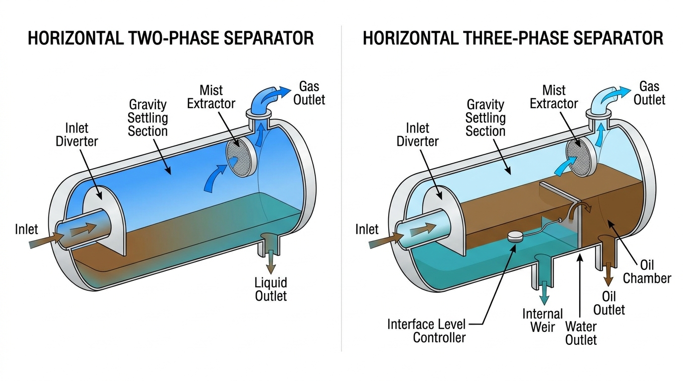
An oil and gas separator is a pressure vessel that splits the mixed well stream into its separate phases: gas and liquid in a two-phase separator, or gas, oil and water in a three-phase separator. It uses gravity, the difference in density between the phases, and enough time for them to settle apart. The separator is usually the first piece of processing equipment the fluid reaches after the wellhead and manifold.
Why Separation Is Needed
Each phase has a different destination. Gas goes to compression, fuel or export. Oil goes to treatment and storage. Water goes to treatment and reinjection or disposal. Pipelines, pumps, compressors and meters work properly only with a single phase. See how separation fits the whole chain in The Oil and Gas Production Process.
The Four Sections of a Separator
1. Inlet diverter
The well stream enters at high speed and hits a baffle, plate or cyclone. The sudden change of direction and speed knocks out most of the liquid, and the gas starts to escape.
2. Gravity settling section
Gas moves slowly through the vessel so that liquid droplets fall out by gravity. The vessel diameter is sized so the gas velocity is low enough for droplets of a target size to settle.
3. Mist extractor
Very small droplets are too light to settle. Near the gas outlet, a mist extractor, such as a wire mesh pad or a set of vanes, catches them. The droplets join together (coalesce) into larger drops that drain down.
4. Liquid collection section
The bottom of the vessel holds liquid long enough for gas bubbles to escape and, in a three-phase separator, for oil and water to separate. A vortex breaker at the liquid outlet stops a whirlpool from pulling gas into the liquid line.
Two-Phase vs Three-Phase Separator
Two-phase separator
Separates gas from total liquid (oil and water together). It is used where little water is produced, or as a first stage before a separate water knockout.
Three-phase separator
Separates gas, oil and water. Water is denser than oil, so it settles to the bottom, and oil floats above it. Internal parts keep the layers apart:
- A weir that oil flows over into an oil bucket or chamber.
- An interface level controller that keeps the oil-water interface at the right height by adjusting the water dump valve.
- Separate outlets and control valves for gas, oil and water.
When the stream has little gas but a lot of free water, a similar vessel called a free-water knockout (FWKO) is used.
Retention Time
Retention time is the average time liquid stays in the vessel. It equals the liquid volume in the vessel divided by the liquid flow rate. The book Surface Production Operations (Arnold and Stewart) gives these typical design values:
Two-phase separators
| Oil API gravity | Retention time |
|---|---|
| 35° and above | 0.5 to 1 minute |
| 30° | 2 minutes |
| 25° | 3 minutes |
| 20° and below | 4 minutes or more |
For most applications, 30 seconds to 3 minutes is enough. Foaming crude may need 2 to 4 times longer.
Three-phase separators (oil phase)
| Oil type | Oil retention time |
|---|---|
| Condensate | 2 to 5 minutes |
| Light crude (30° to 40° API) | 5 to 7.5 minutes |
| Intermediate crude (20° to 30° API) | 7.5 to 10 minutes |
| Heavy crude (below 20° API) | 10 minutes or more |
For the water phase, 3 to 30 minutes is common. The same book recommends 10 minutes for design when no laboratory or field data are available. If an emulsion is present, the oil times may need to be 2 to 4 times longer.
Horizontal vs Vertical Separators
- Horizontal: a large gas-liquid interface, so better for high gas rates, foaming crude and three-phase separation. Usually smaller and cheaper for the same capacity. Takes more floor space.
- Vertical: better for streams with low to moderate gas-oil ratio, sand, or large liquid slugs. Uses little floor space. Often used as gas scrubbers.
- Spherical: compact but with limited capacity. Rarely used today.
Production Separator vs Test Separator
A production separator handles the combined flow of many wells. A test separator receives one well at a time so that its oil, gas and water rates can be measured. This is the basis of well flow tests.
Stage Separation
Many facilities use two or three separators in series at falling pressures, for example a high-pressure, a medium-pressure and a low-pressure stage. Stage separation keeps more light hydrocarbons in the liquid, which increases stock-tank oil volume, and it lets gas be recovered at higher pressure to reduce compression needs.
Common Operating Problems
- Foaming: reduces separation capacity. Treated with defoaming chemicals or larger vessels.
- Emulsions: oil and water that will not separate easily. Treated with heat and demulsifiers.
- Sand: settles and fills the vessel. Removed with sand jetting systems.
- Slugs: sudden large volumes of liquid. Handled with extra surge volume or a slug catcher.
- Liquid carry-over and gas carry-under: usually caused by overloading or poor level control.
Frequently Asked Questions
What is the difference between a two-phase and a three-phase separator?
A two-phase separator splits gas from liquid. A three-phase separator also splits the liquid into oil and water.
How does a separator control pressure and level?
A back-pressure valve on the gas outlet holds the vessel pressure. Level controllers open and close the oil and water dump valves to keep liquid levels steady.
What is a scrubber?
A separator designed for streams with very little liquid. It removes droplets from gas before compressors or fuel systems.
Conclusion
Oil and gas separators use gravity and retention time to split the well stream into gas, oil and water. Knowing the four internal sections, the difference between two-phase and three-phase designs, and typical retention times is the foundation of surface production operations.
Next in this series: Part 10, Oil Well Production Problems.
Leave a Reply